My FG (MK2) ZF flappy paddles...
I started seriously thinking about flappy paddles for my [one owner, 43,000km's

] 2012 FG MK2 XR6T (LE) a few months ago. I had seen the flappy paddle mod available on ebay a few years ago that was stuck high up on the steering wheel column, but I didn't like it for a few reasons I won't go into here. It's good to have a red hot go after all, and good on 'em for making it.
I've also been playing around with some microcontrollers for years now for various projects, and have moved on through some different models from the old Mega328P 16MHz based ones to some nice ESP8266 WiFi modules that run much faster and even on to ESP32S that are fantastic. Here though, the cheap ESP8266 ones came to mind for sending radio signals from inside the steering wheel to the gear shifter, which seemed like a neat way to implement some paddles without a lot of extra wires... Until I worked out the only power source inside the steering wheel was the horn's 12v wire, through its relay coil. So I started thinking from scratch again, not wanting to mess with the horn.
At this stage I was convinced that I'm very limited with respect to mounting something new on the steering wheel itself - but I then thought there's already some buttons on the wheel which I could re-purpose (no, I hadn't searched any forums for ideas, but once I was done I did find this forum thread that also shares the same idea). I ordered some original FG steering wheel buttons from ebay to play around with, because I really didn't want to screw with my car at all. I can see they are a pair of resistor-to-resistor networks that change total resistance depending on the button pressed. The nice thing here is, only one button will be detected at a time on each side (press two on one side and one button always takes priority)... I recorded the values I saw with my meter and calculated the differences. Only later, I found a download for the car's wiring schematics that had all this information!
Hmmm, back to the trusty Mega328P. It has the ability to interface with these types of analog signals fairly easily, it has loads of output pins that might be needed, so I coded up some firmware to report back which buttons were being pressed. Easy. My next problem to solve though was keeping as much functionality in the car as I could, which meant solving a few problems:
1/ How to replicate back to the car what the buttons were originally doing, but by using the microcontroller.
2/ How to detect what mode the car was in (Auto/Sports, and if the gear shift +/- was currently in use).
3/ How to control the +/- functions of the gear box from the microcontroller.
4/ How to prevent limp mode if the transmission sees some signals that shouldn't happen.
5/ How to install this device without screwing with the car in a permanent way!
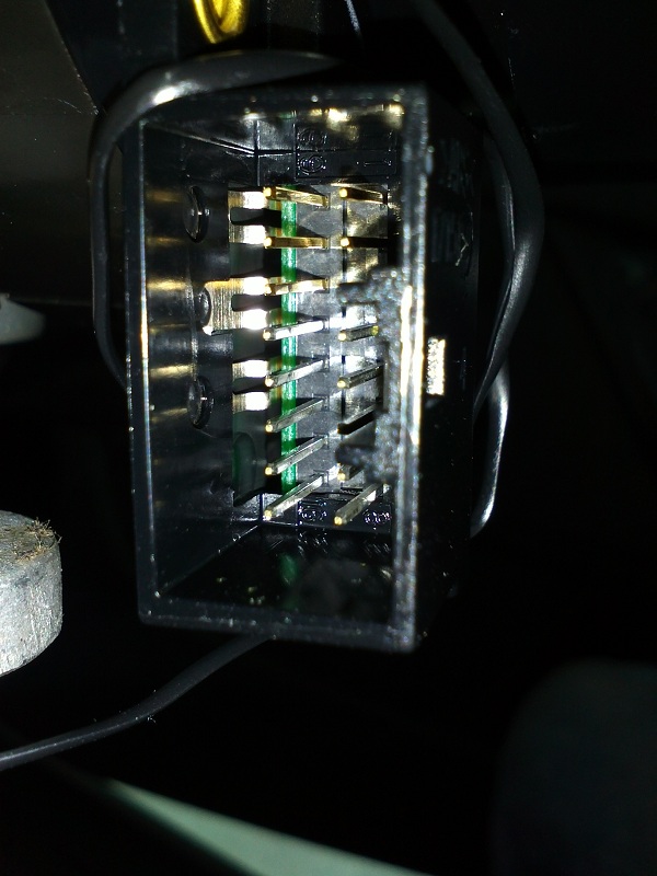
Point 1 was a bit tricky as I didn't know much about the car's wiring. After reading the wiring schematics, it also turns out my car is different to the documentation... The steering column [clock spring] socket:
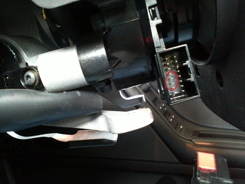
has 4 pins in a row for the two sets of buttons, which when I look at the schematic, go [GND, L-Signal, GND, R-Signal] but my car has them wired up as [GND, L-Signal, R-Signal, GND]! My initial thoughts of using some signal level transistors would surely not like being plugged in without knowing exactly which wires were which because the polarity matters.
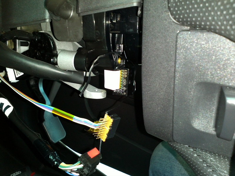
Here's the car's plug that goes into the clock spring socket:

This is the circuit that is drawn differently to how my car was built:
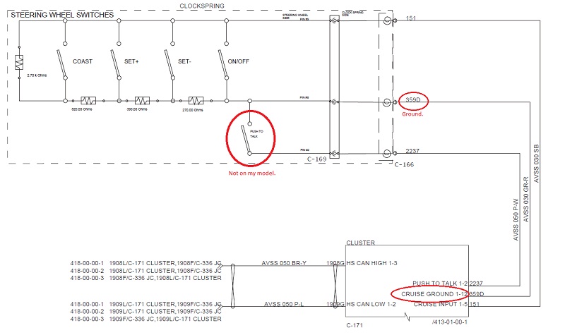
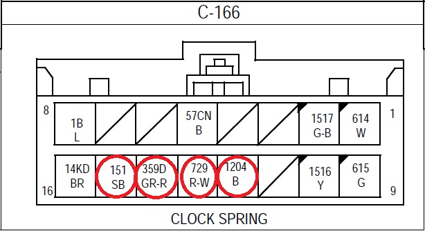
You can see pin 359D=ground and 151=signal in the diagram (my car doesn't have pin 2237 or the push-to-talk button). Here is the plug's pinout, where on my car 151=ground and 359D=signal. Both my car and the schematic diagrams show the radio buttons as being on 1204=ground and 729=signal so that's good. From what I can see, 1B=horn-relay (+12v) and 57CN=horn-ground. 1B, 614, 615, 1516 & 1517 are used for the steering wheel's air bag. 14KD is unknown to me! I can see an extra wire too on my plug, which isn't documented.
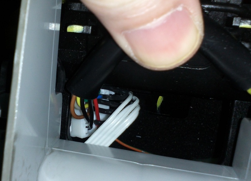
Thinking about how point 5 could be solved, I'm going to isolate those 4 pins I need using an interface board. Since the original plug won't be fully inserted [and locked in place] anymore, I need to work out how to use a wire tie to keep it all together - I've wrapped it around as shown here:
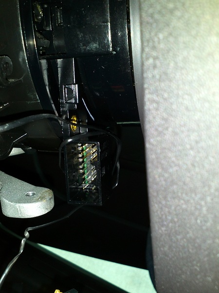
But wait, what's that inside the socket? Turns out, it's 3 fail safe sprung metal tab "switches" to tell if the plug is loose, which can give an airbag warning:
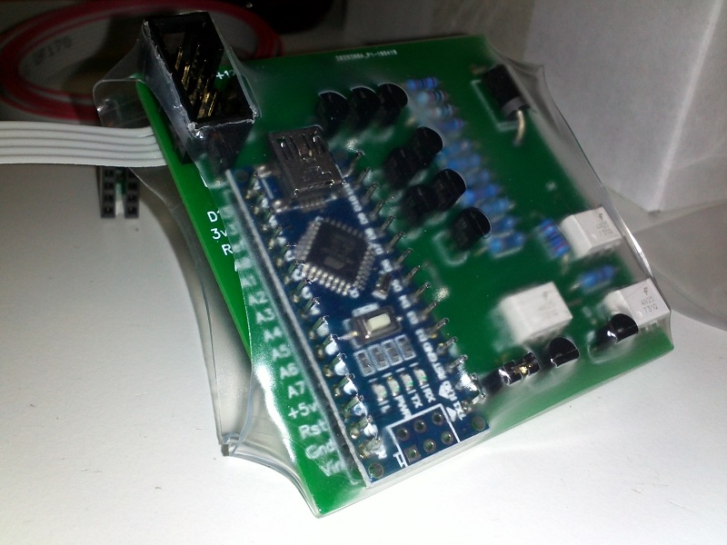
My interface board and kapton electrical tape insulator (on thick-ish paper card) to bypass those fail safe switches:
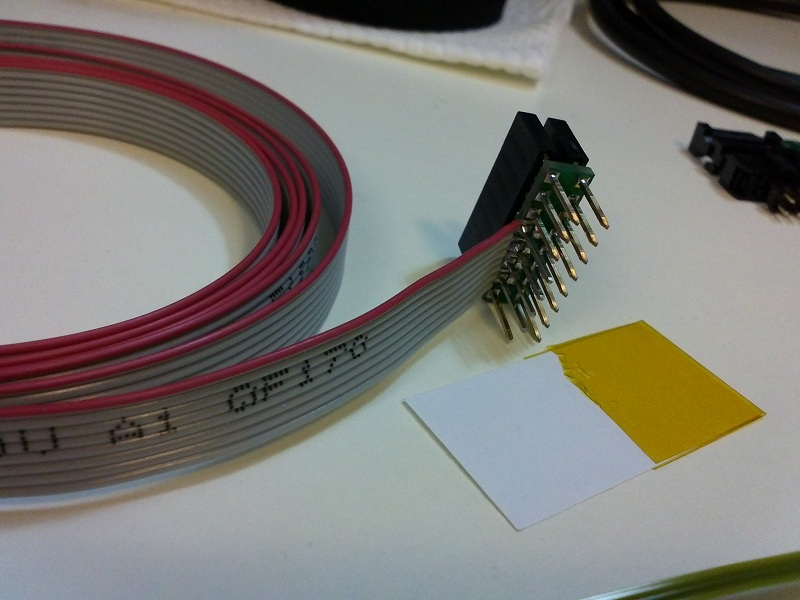
My full kit, almost finished. Here, I'm going to use thick copper wire [on the right hand end of the grey ribbon wire shown in the middle] to interface with the existing transmission shifter plug - so I don't have to cut any of my car's wires or do any soldering to the car:
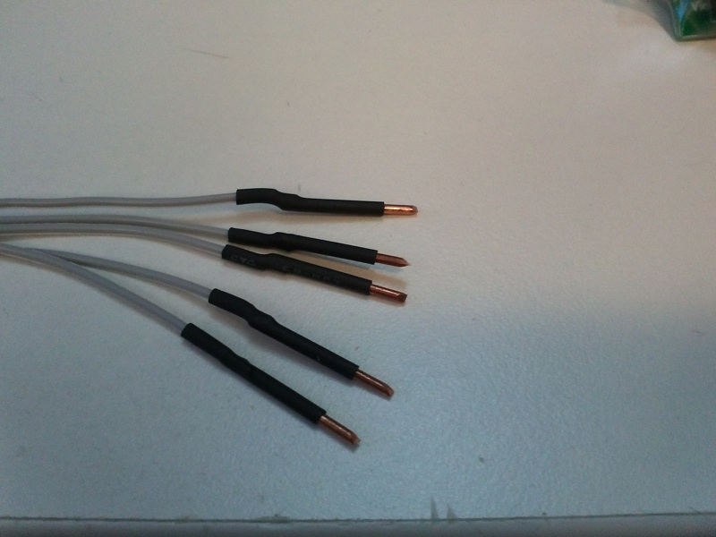
Close up of the thick copper wire:
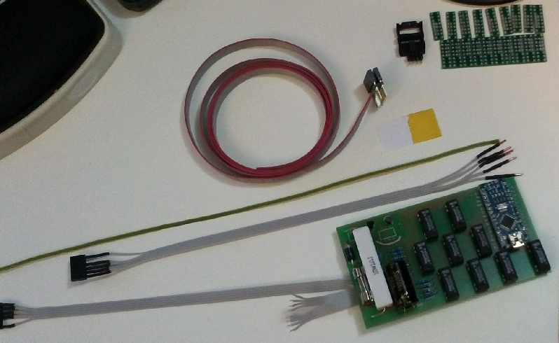
I'm also now testing another design with signal transistors for the R-to-R resistor button networks, to be used if it's known how the car's steering wheel plug is wired - $45 extra in relays for the first model just sucks. This one is wrapped in heat shrink tubing and is a much smaller circuit board to the first one I made earlier:
Back to the steering wheel... Insulator paper card fully inserted to make sure the 3 metal tabs don't short out the plug's wires (which the car detects as a loose plug):
New interface board plugged in (this is a photo of my original prototype, I did have nicer circuit boards made up later as shown in the picture above):
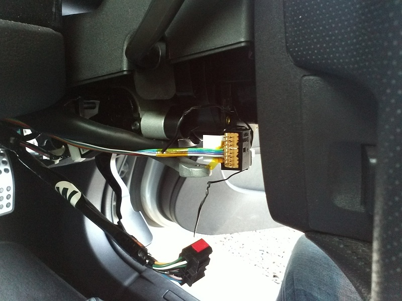
Original plug, back where it needs to be with the cable tie wrapped around it all [through the vertical centre of the plugs wires] ensuring it won't come loose while driving:

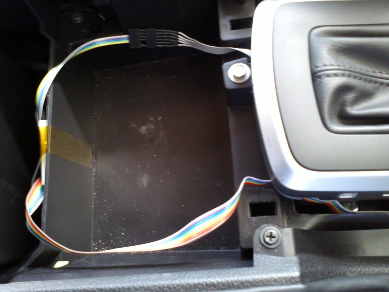
Ribbon cable [my prototype used coloured ribbon cable, not grey like in the other photos] threaded through the centre console. The black top cover of the centre console just pulls up and off for access:
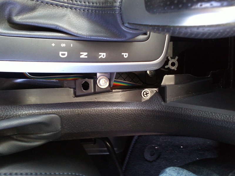
Inside the gear shifter module... I obviously didn't want to completely rip out the centre console to get this working so squeezing the leather trim edges of the shifter inwards at the centre and pulling it up gains access to the inside here:

To get access to the back of the transmission's connector, I used the handle (non sharp) end of a screwdriver and prised/pushed it toward the passenger side to unhook it from its mount. Then pulled up on the wires coming from the gear shift circuit board to move it into a suitable position to work on. Using some long nose pliers, I slid in the thick copper wire shown in pictures above and they are held in place by friction. Once done, I threaded the short cable through/underneath, and out the back of the shifter module.
Connector C-318:
|--------------|
|BP|B.|BR|GR|LY|
|LR|..|..|SB|G.|
|--------------|
...|_......_|
My 6 Pin Plug for the Paddle Shifter mod coming out from the gear plug:
+12v (green/G)
N/C
GND (black/B)
MGATE (blue/SB)
TIP+ (grey/GR)
TIP- (brown/BR)
The cable looks like this, so I can easily see the missing pin to make sure I don't plug it in backwards:
---|
...|\____
---|_____~
---| ____~
---|/
---|
(Had to replace spaces with dots for that to show correctly.)
(Leave unconnected)
Black+Grey/BP
Light-Red/LR
Light-Yellow/LY
The nice thing about the +12v wire here is it's the battery saving power source - so the new circuit all turns off after 15 minutes once I stop driving:
Both cables through the console and to my microcontroller:
Tape the microcontroller in place with some strong kapton electrical tape:

Those two ribbon cables were later taped to the side walls so they were not moved when putting back the black centre console cover.
The firmware I programmed does some nice things... All the steering wheel buttons work as they normally would when I'm in automatic mode. When in manual mode though, I figure I'm probably not interested in turning on cruise control or playing with the stereo source mode... So those paddle buttons now control gear shift up/down. All the other buttons continue to work as normal (volume / cruise resume etc.) at all times. If I'm using the original gear shifter for +/- (for example, while turning a corner when the steering wheel is upside down) it will very temporarily lock out the new paddle shifter signals. The paddle shifters themselves will only send a very short once off signal to the gear box, meaning I can continue to hold those buttons and not worry about the original shifter conflicting if also used soon after (it will override what was last sent to the gearbox). If, somehow, (and I've not knowingly managed to do this myself) I send a gear shift change using the new paddle shifters, and then also, slightly afterwards but within that very short time frame of the microcontroller's once off signal, send an opposite signal using the original shifter, the microcontroller will sense it and almost immediately discontinue the paddle shifter's signal early. I suspect the AT unit will do a 2nd check (or more) before engaging limp mode, but it will no longer see the two signals occurring at once by that time.
The very first time I drove my car with it all set up, ignoring the air bag warning that went off (which took 3 hours to work out why), I found it difficult to control. I was constantly in the wrong gear, clumsily trying to get it corrected. As soon as the wheel was turned slightly, I didn't know which button to press to change gear. Then, with about 10 minutes of driving (going for a longer drive after fixing the air bag warning issue) it all sunk in... I now love it and I'm not going back.

Oh, some last comments, it's not possible in the firmware logic I wrote for the very short up/down signals [from my microcontroller] to the gear box to happen "at the same time" [by pressing both up and down shift on the steering wheel buttons] as the left/right button logic is tested and processed sequentially not asynchronously. I.E. one may occur, then the other may occur, but never both at the same time. Since I have previously been in a "panic situation" of wanting to slow down in an emergency [another story, another car
] holding both buttons in panic will allow the "down shift" to override the "up shift". Safety first
Parts for this kit cost me around $75, I ordered some of the more expensive bits from China, it would be about $110 if purchased in Australia. The professional circuit boards I designed and then had made in China blew out that budget even more. The newer model without relays, that I'm testing now, costs about $30 in parts ($75 if bought in Australia) but then I wanted a nice circuit board for it too. It also takes me about 3 hours to assemble either version, and some more time still to fully test them on the workbench so I'm confident it won't hurt my car. I think if I were to make them for sale though, it would have to be a little overpriced for what it is because it takes so much time and effort, which is a shame.
It also takes around an hour to install, which is mostly bent over the driver's seat, trying to use pliers to push in the thick copper wire into the back of that socket, while resting on my elbows! The steering wheel part isn't as bad, but threading the ribbon cable through the console was a bit hit and miss.
Great fun though