I was contacted by Ren a few weeks ago (AFF member 2.8L Hilux) about my flappy paddle project and he mentioned he had a BF Falcon with a ZF! (Awesome.) It got me thinking, it shouldn't be too hard to make it work on a BF, all I needed to know was the steering wheel button's resistances. He said the BF buttons were a slightly different configuration to the FG's so he thought the ones to re-map should be seek and resume-coast. I wasn't 100% convinced, until I received my next package from ebay in the mail (at half cost of the FG ones):
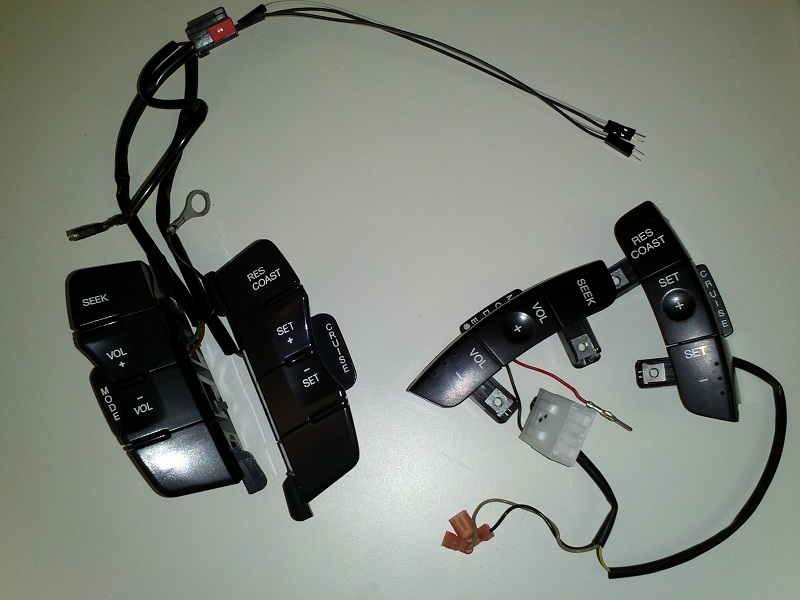
(Yeah, I know, two sets of flawless looking buttons sitting in my R&D box.)
So I went about repeating the process. Pulled out the red-wire-pin to measure and searched for some connectors that closely matched (I'm sure I know the brand, but I went with some different ones that had identical dimensions):
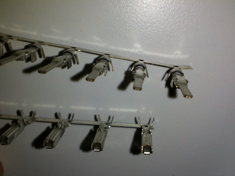
Which are 345807-1 & 345206-1 models from the 070 econoseal III contact line of products. I had taken a leap of faith that the clock-spring connectors would all be the same, which turned out to be true.
So, having tested the buttons with my meter, picked the correct resistor values to make an R-to-R network that matched, and measured the new values with the microcontroller.. I created a kit for Ren all programmed up:

A few less resistors were needed, and one less transistor too.
You can hardly see it, but there's a grey wire loop on the left of the blue circuit board folded under the green one, if it's cut, then the device will revert back to the mode/cruise buttons for shifting just in case thumbs are not as good as fingers

These are the instructions I supplied:
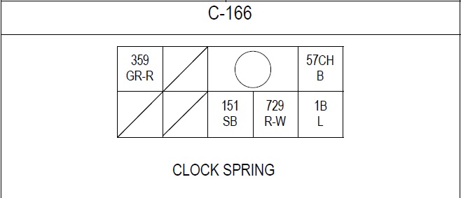
Plug connector from car-computers to the Clockspring socket front view:
.----- ----- ----------- ------
| 359 |.....|.....O.....| 57CH.|
.----- ----- ----- ----- ------
|.....|.....| 151 | 729 |..1B..|
.----- ----- ----- ----- ------
Clockspring's socket receptacle front view: (mirror view to the plug above)
.------ ----------- ----- -----
| 57CH |.....O.....|.....| 359 |
.------ ----- ----- ----- -----
|..1B..| 729 | 151 |.....|.....|
.------ ----- ----- ----- -----
Clock Spring Plug/Socket wire numbers and their function:
359 (GR-R) = Ground [Cruise Control]
151 (SB) = Signal [Cruise Control]
729 (R-W) = Signal [Radio]
57CH (B) = Ground [Radio & Horn]
1B (L) = +12V [through Horn relay coil]
My ribbon wire and which side & pin they connect to:
1 = Ground Radio Buttons Side 57CH socket\_+BLACK WIRE
2 = Ground Radio Device Side 57CH pin..../ FOR THE HORN
3 = Signal Radio Buttons Side 729 socket
4 = Signal Radio Device Side 729 pin
5 = Signal Cruise Buttons Side 151 socket
6 = Signal Cruise Device Side 151 pin
7 = Ground Cruise Buttons Side 359 socket
8 = Ground Cruise Device Side 359 pin
And 1 single wire for the +12v horn relay connection which my device doesn't need.
You can see the ribbon wire has wires 1 & 2 connected with a thicker black wire, so that's where to start. Once it's all done, I guess, use some electrical tape to secure it in place so if you pull on it, it doesn't all come undone. I.E. tape the end of the ribbon wire to the car's existing harness.
If you don't get it right (and as long as the +12v hasn't been plugged in incorrectly) there should be no effect on the car other than the radio / cruise functions being activated immediately or when accessories is on. Just try again. Maybe only plug that single +12v wire in once you're done? That's the only one that can possibly damage my device - and if it's wrong, the horn will probably go off right away giving you the scare of your life!
Ren did send through one image that looked familiar to me, but wasn't what I had seen before: (I don't know how he got such good access to the plug! The FG has it locked away...)
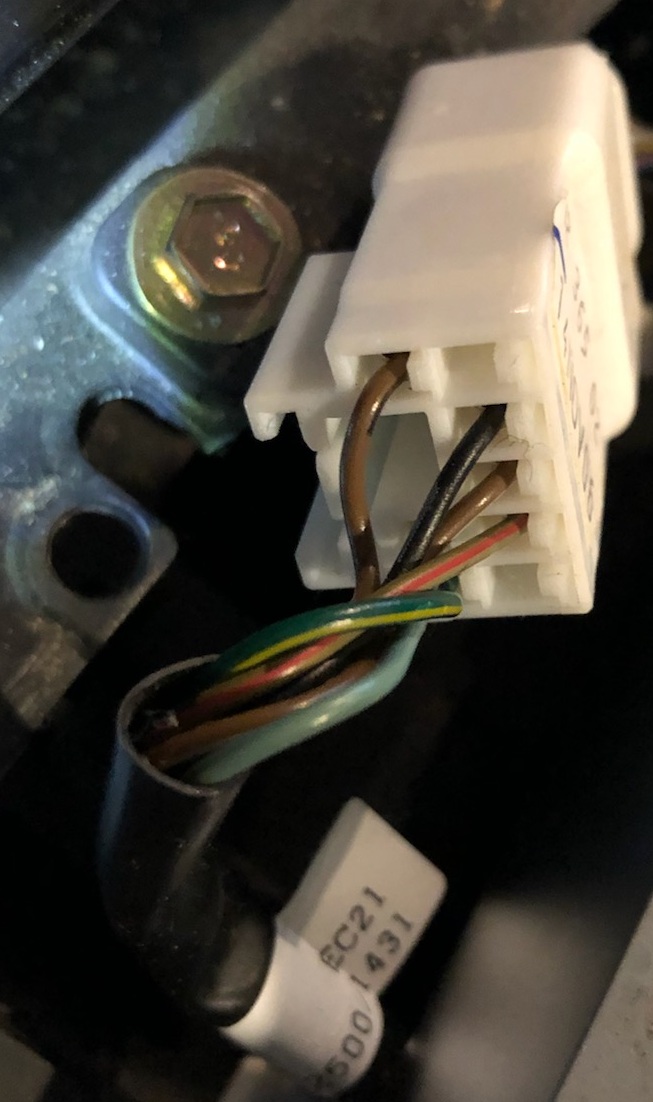
Which is the BF MKII gear shifter plug, which has less wires and different colours to what the FGII has. I could see the wires that were there are in the same place as what I had described before though, for the ones I needed, and the circuit diagram I have for the BF said they were the ones to use, so I suggested that looked OK to continue.
Both Ren and I thought the copper wire inserts were a tight fit, but long nose pliers worked well for us both. And the result? See the last post on page 2 of Ren's V8 BFII Fairmont Ghia show and shine thread:
http://wwww.fordforums.com.au/showth...1478318&page=2
Anyhow, it's good to know that quite a lot of the parts in our cars share such similar heritage. Although Ford was having a "brown wire" day when the BF was being designed! I'm really glad Ren had a good experience with this mod. He paid me more than I had asked, so I got a free lunch! Thanks man!
Not wanting to say, but $200 + overnight-postage of $11.55 was my estimate for what it cost me in parts and time to make it for him. I might be convinced to make some more, if the instructions are not scary to whoever's interested.