
|
|

|
|
|
|
|
 06-10-2019, 12:14 PM
|
#1 | |||
|
FF.Com.Au Hardcore
Join Date: Jun 2010
Location: Perth
Posts: 1,315
|
Quote:
Then there should be a secondary VIN, when a module has been re-purposed, and matched to a new vehicle. It will keep that VIN also in a different location, but not remove the initial one. Ford's IDS in expert mode (engineer) can see all original VINs. I heard a comment from the dealer /programming specialist: 'once we had a dodgy FG come to the workshop, where all the modules originated from a mix of 3 different vehicles'.
__________________
'11 FG Turbo '08 Territory SY RWD And some non-fords: E90 M3 build, '07 Rocket III, |
|||

|

|
| 3 users like this post: |
|
06-10-2019, 12:29 PM
|
#2 | ||
|
FF.Com.Au Hardcore
Join Date: Nov 2013
Posts: 2,037
|
Looking at this screenshot, looks like Forscan can update the FDIM VIN if you've got a used one to go in. https://forscan.org/forum/viewtopic.php?t=7123#p30168
|
||
|
|
|
|
06-10-2019, 12:44 PM
|
#3 | ||
|
Away on leave
Join Date: Apr 2019
Location: ACT
Posts: 1,732
 
|
Ha ha! Yes, that's what I used to see Forscan try 6 times but fail each time.
It kicked me out of the FDIM settings when it failed. Then I tried the FPV setting and it did the same. That was on my original unit. Then I tried on the SAT NAV unit and FPV enable worked, but still couldn't set the VIN. These devices check the settings, it's not a forced write. An example is when the error code comes back on the CAN BUS for settings the VIN. Since setting the VIN is a multi packet CAN message, the error comes when it detects one of the VIN digits isn't "right". If you change the letters up front, you don't get to pass the rest of the packets because an error is returned early. If you change the last digit, the device accepts all packets up to that last one before giving you a response. The response seems to be error (in one packet) or success (seems to produce two packets). |
||
|
|
|
|
06-10-2019, 07:09 PM
|
#5 | ||
|
Away on leave
Join Date: Apr 2019
Location: ACT
Posts: 1,732
|
Oh, ok. That's interesting. It might be the config profile loaded?
I've been playing with the ACMs today. Now that Forscan has "calibrated" the code (which BTW I don't see it sending my VIN into the unit - only a calculated 3 byte value each time you run the calibration routine) I can get it turned on and tuned to some AM station on the bench with my car's CAN-BUS recording. I can also adjust the volume with my spare steering wheel buttons. This is much better than soldering on some new wires and re-assembling it to fit in the car to test out. It's nuts though! If I connect an AMP's input (I'm using a rear speaker for my tests) anywhere near the car-ground, then it gets all noisy. I was trying to attenuate the signal so there would be less hiss, with the drawback that you need to turn up the volume (doing so doesn't change the hiss level). So instead of a 40w system, it would be a 20w system but much better quality.. Sort of ready for some add-on 3rd party amp talked about previously. It's not happening though. Confused about the quality of the MKI radio, I had a play with it too. Yep, nice and quiet. Cutting an AMP's leg and doing all my usual tests, no sound at all! The damn thing turns off the AMP when it's got nothing to output. Turn the volume all the way down, AMP turns off. Turn it up just one notch, and the same hiss that the FG2 has can be heard. Since the screen in the MKI doesn't use the radio's ICC speaker inputs, I guess it thinks it can do that where the MK2 needs to keep it on all the time in case the ICC needs it. Sadly, there were no answers in the older model. |
||
|
|
|
| This user likes this post: |
|
06-10-2019, 07:27 PM
|
#6 | ||
|
Away on leave
Join Date: Apr 2019
Location: ACT
Posts: 1,732
|
Oh, I forgot to add.. In my tests, I've connected a switch (no, not the big one) so I can hear old vs new-mods. There is identical hiss when I traced the speaker line back to the largest chip on the circuit board (clearly a sound processor - which has 4 raw speaker outputs) and used the recommended 0.22uF cap. for the AMP vs the numerous components (and there are a lot) on the board. Identical sound too when the volume is turned up. The hiss is either in or before that sound processor micro-chip.
I even connected up another AMP to one of those outputs and there's hiss, along with ground noise. There is no fixing this unit, only working around it, if I can get the attenuation circuit working. |
||
|
|
|
|
06-10-2019, 07:38 PM
|
#7 | ||
|
FF.Com.Au Hardcore
Join Date: Nov 2013
Posts: 2,037
|
Have you tried looking at the ACM data blocks? A common improvement in the FG was to swap the wires going to the sub to reverse the phase. I wonder if that can be done with a config change.
|
||
|
|
|
|
06-10-2019, 07:53 PM
|
#8 | ||
|
Away on leave
Join Date: Apr 2019
Location: ACT
Posts: 1,732
|
I did look, but there are 7 blocks (block 2 is the VIN) while blocks 1 and 3 are small, 4-7 are all quite large and wouldn't be easy to decipher. I recall Forscan only had 2 items you could adjust, Reset Centre Level and Sedan/Ute.
You're right though, there may be a switch for options that introduce the hiss? |
||
|
|
|
|
06-10-2019, 10:39 PM
|
#9 | ||
|
Away on leave
Join Date: Apr 2019
Location: ACT
Posts: 1,732
|
Success!
I found the Japanese PDF for the large chip (no I don't read Japanese!) but it had an example circuit that I could read. Like the Arduino, there's an audio ground that remains much quieter from the general ground... The pin outs are in a different order to the AMP chip (AMP is on the right, audio chip is along the bottom): 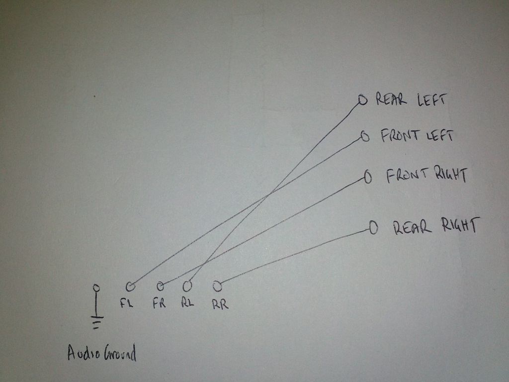 Here are the first-in-line surface mount devices I'm going to hook into: 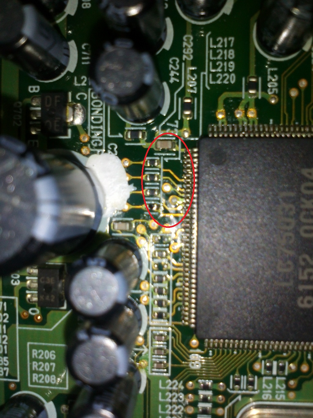 Solder the wires on: 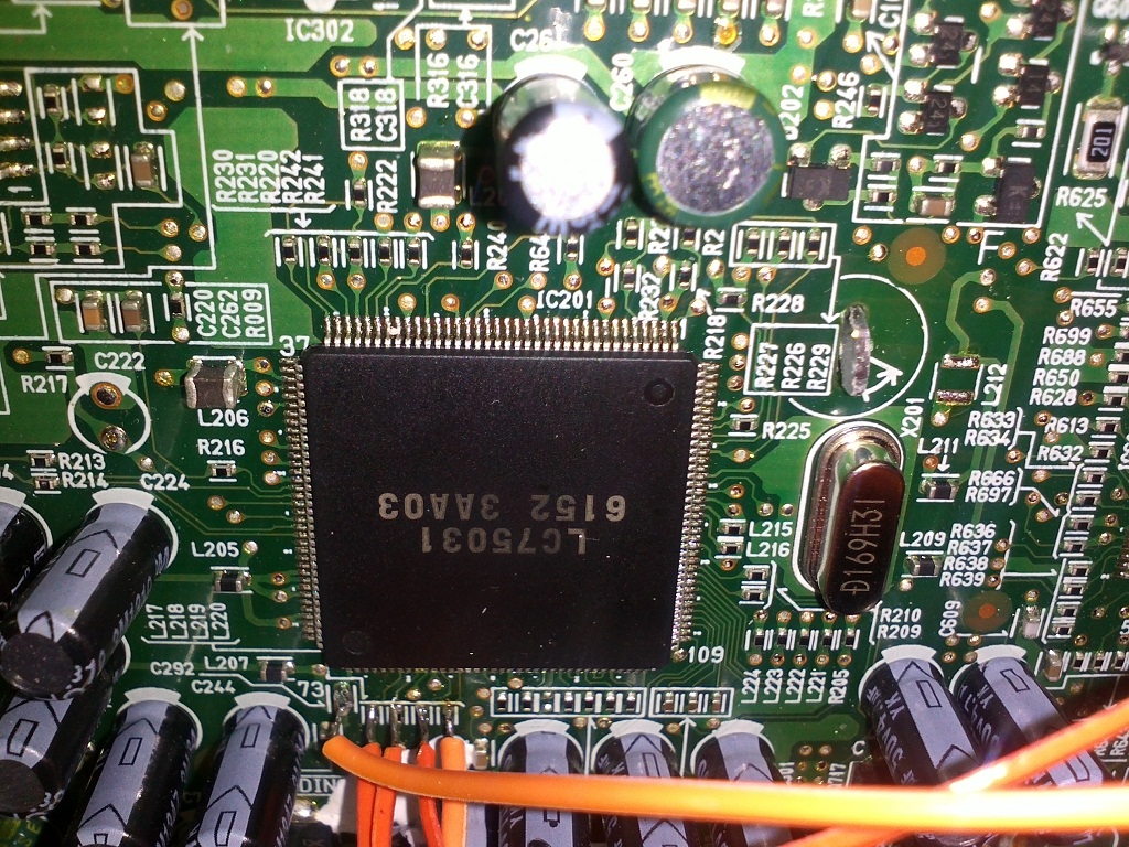 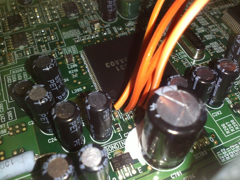 Wires go to a bunch of resistors: 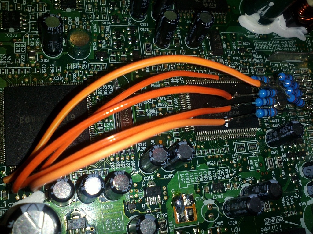 Resistors go to the capacitors which are connected to the cut AMP inputs: 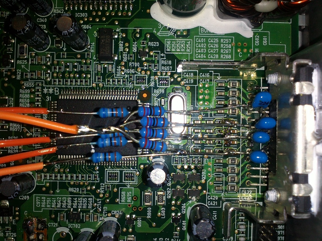 The whole unit: 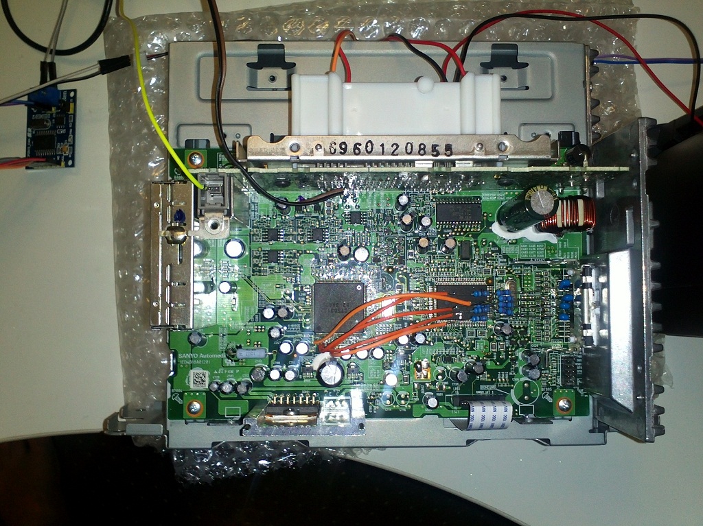 So I'm using a voltage divider (a couple of resistors) to attenuate the output from the audio processor (car AM/FM +inputs radio chip): Four of these: Output--->6.8Kohm--->0.22uF--->AMP-Input AGround--2.7Kohm--^ I'm using the blue resistors (1% accuracy) so the end result doesn't need fader adjustment. The hiss has been reduced to about 1/3 (maybe a bit more). When I listened to the radio before, I had the volume on about 13. Now I have to bring that up to about 20 (which doesn't increase the hiss). I'll see how this goes tomorrow while driving, it's too late for a drive right now. Sitting in the carport though, it was so much better. |
||
|
|
|
| 2 users like this post: |
|
07-10-2019, 11:37 AM
|
#10 | ||
|
Away on leave
Join Date: Apr 2019
Location: ACT
Posts: 1,732
|
Went for a drive, had the volume up at 24 - before when driving it was at around 16 (13 was when parked). Very clear sound, the mod has not introduced any extra noise. The volume goes up to 35, which I've never done before when music was playing, and now it is reasonably loud at that max level. Nothing earth shattering, I might have it that loud in rare circumstances (who am I kidding, I'm too old to want that).
But the hiss is so quiet now. Definitely less than 1/3 of the original noise. Very happy 
|
||
|
|
|
| This user likes this post: |
|
07-10-2019, 03:09 PM
|
#11 | ||
|
Away on leave
Join Date: Apr 2019
Location: ACT
Posts: 1,732
|
Do you have a multimeter? The red/black screen power wires should read 9v - which is where I'd look first.
Here are some picks of my working unit:  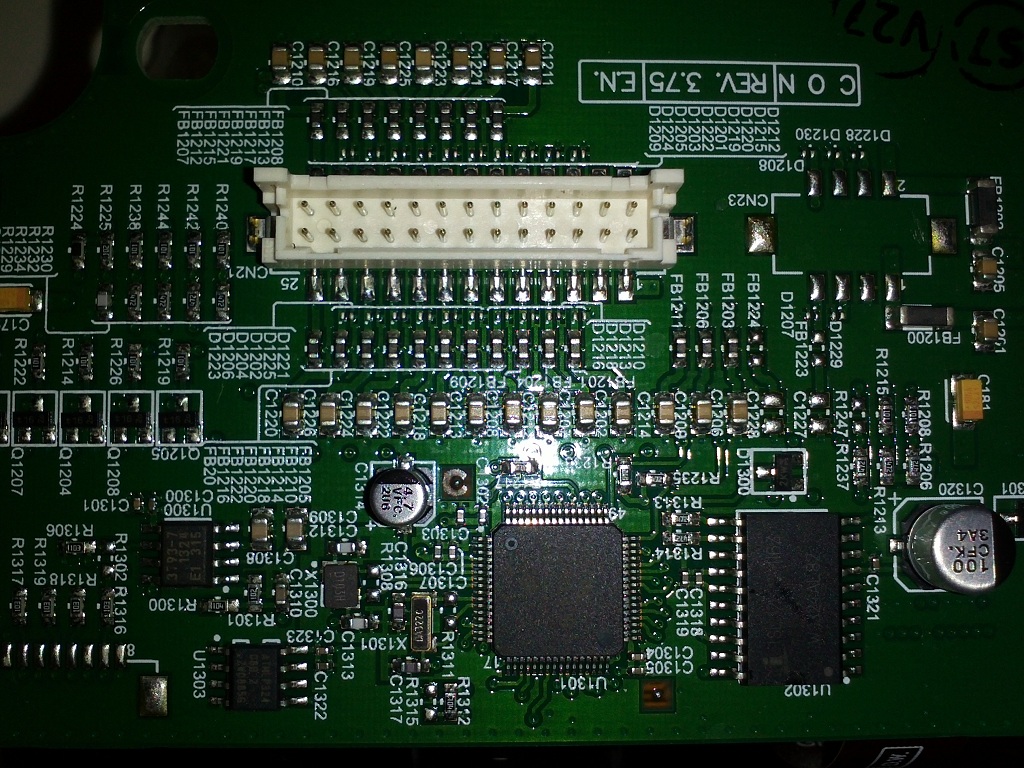 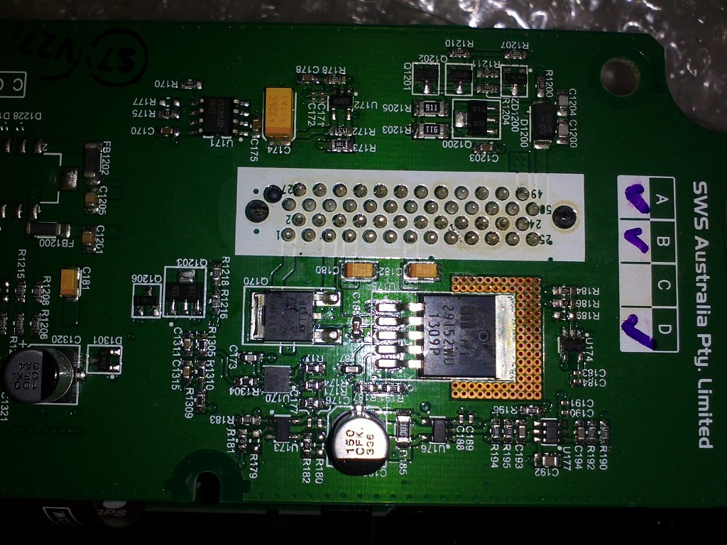 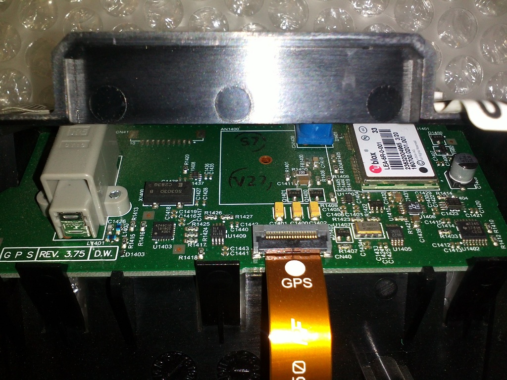 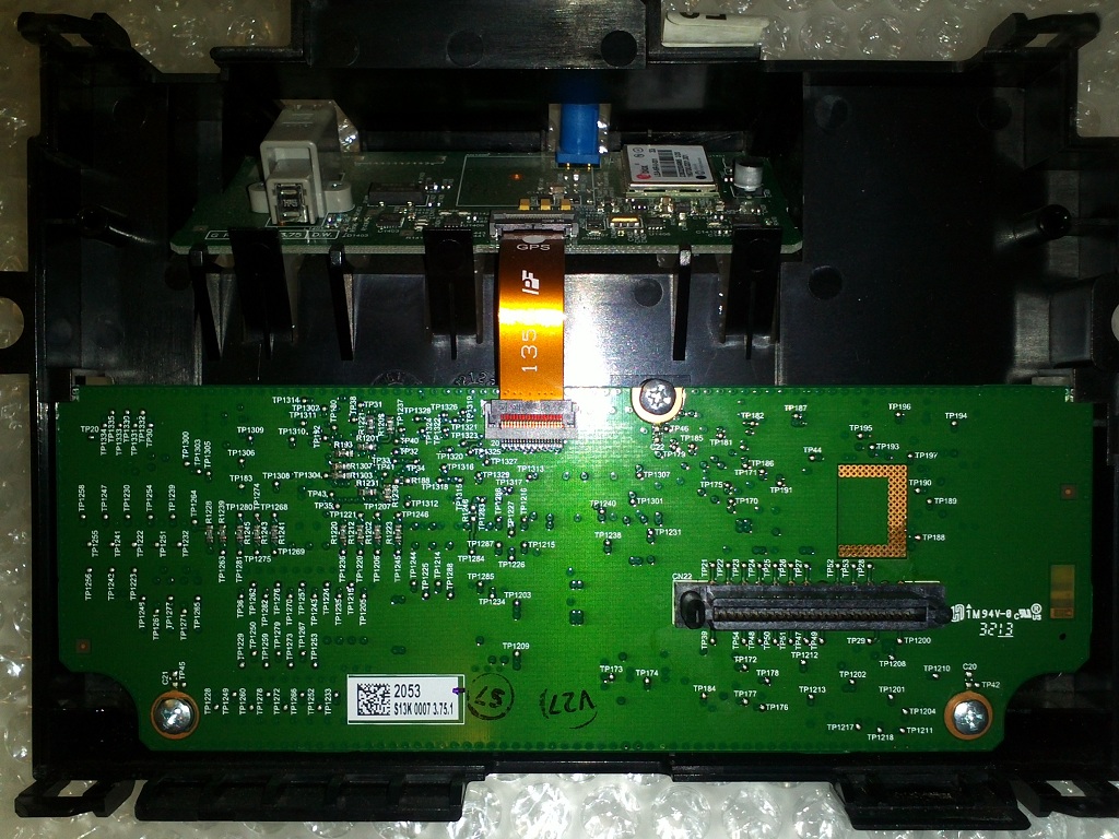 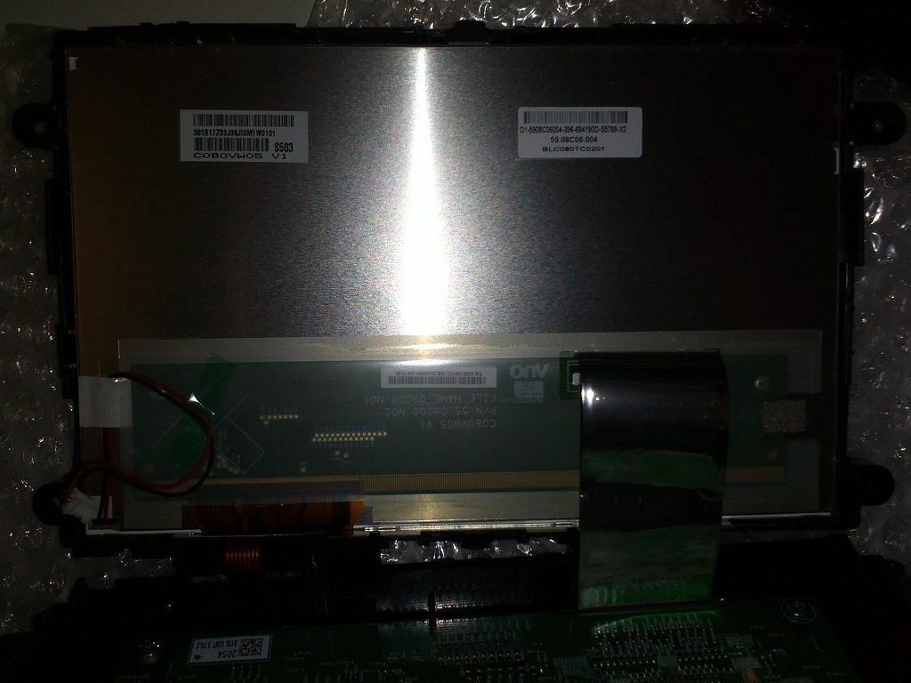 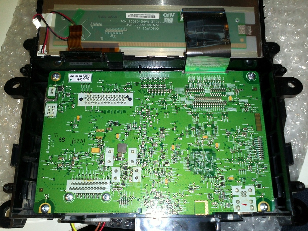 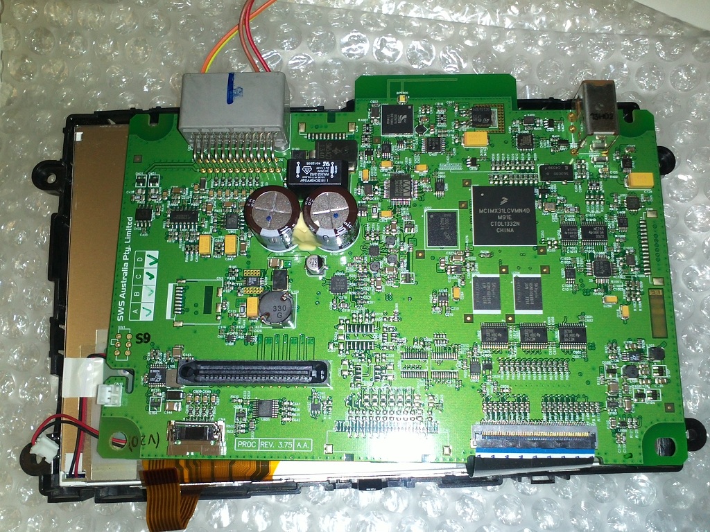 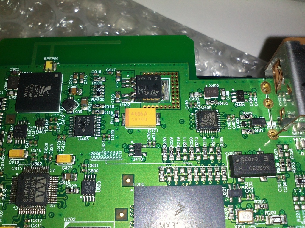 (Sorry, I'm just reassembling my car door - be back later.) |
||
|
|
|
|
07-10-2019, 03:41 PM
|
#12 | ||
|
Away on leave
Join Date: Apr 2019
Location: ACT
Posts: 1,732
|
Ok, car door's back in...
These are my notes on the FDIM: 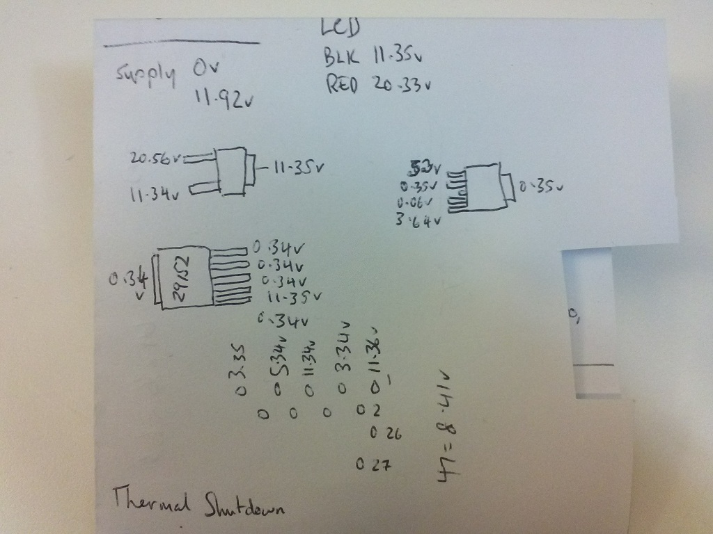 According to the car ground, the black and red wires are ~11v & ~20v which gives 9v to power the screen. The two devices on the left are on the small controller board, see first & third pictures. The one on the right is the large controller board's LF33 3.3v regulator, see last picture. I also measured quite a few of the pins connecting the two boards together. I stopped writing them down when I could see they were all the same, except pin 47 which had an odd mid-range voltage. "Thermal Shutdown" was shown to me on the screen after I took all these measurements, doesn't seem to have been any permanent issues though. |
||
|
|
|
|
07-10-2019, 04:01 PM
|
#13 | ||
|
Regular Member

Join Date: Oct 2019
Location: Adelaide, SA
Posts: 43
|
Hi Jason,
I just check the red/black wire to the LCD, and i am not receiving 9volts. :( Also, what are you using to power the FDIM at your desk? |
||
|
|
|
|
07-10-2019, 04:05 PM
|
#14 | ||
|
Away on leave
Join Date: Apr 2019
Location: ACT
Posts: 1,732
|
2.0A - 12v adaptor from a "portable" hard disk.
You need the two boards connected together too, most of the power comes from the smaller board - even though the power inputs are on the larger one. |
||
|
|
|
|
07-10-2019, 05:24 PM
|
#15 | ||
|
Regular Member
Join Date: Oct 2019
Location: Adelaide, SA
Posts: 43
|
ok,so i did some bench tests, and without the red/black wire connected i get 2.5v and with it connected i get -0.5v.
|
||
|
|
|
|
07-10-2019, 05:48 PM
|
#16 | ||
|
Away on leave
Join Date: Apr 2019
Location: ACT
Posts: 1,732
|
Bench testing requires a CAN BUS recording from a car being played into the unit, depending on the unit (firmware) it might turn on for 10 seconds when power is initially applied (after 20 seconds). My one from 2012 doesn't even do that, the one I've replaced mine with does - it's a 2014 model with newer firmware. What's yours?
If I didn't have the CAN BUS stuff, I would be testing the voltages while in the car. You can see where the 20v and 11v are coming from, on the small circuit board. I don't think it's hard to measure those while in the car, as long as it's been unscrewed from the back cover. It might be obvious from a picture, as you said, there's residue on yours? |
||
|
|
|
|
07-10-2019, 06:54 PM
|
#17 | ||
|
Regular Member
Join Date: Oct 2019
Location: Adelaide, SA
Posts: 43
|
I have a 2013 fg xr6, tested the voltage of the red/black wires from within the car, and still didnt get 9 volts.
Below is where i could see a lot of residue. |
||
|
|
|
|
07-10-2019, 07:31 PM
|
#18 | ||
|
Away on leave
Join Date: Apr 2019
Location: ACT
Posts: 1,732
|
The only thing I see which looks bad in that photo is the part-number on the 5 pin device. It could be heat damage that has faded it on yours (neither of mine look like that - I didn't take photos of my 2012 one because it looked exactly the same as the 2014 one except the GPS wasn't there).
It's a voltage regulator - low dropout model with 1.5A capability. Looks like it's an adjustable one so I don't know the voltage it's meant to have. I'll have to take my readings again, based on the schematics I downloaded, the only thing mine is doing is accepting the 12v input voltage. The enable pin is telling it not to output the regulated power. I'm almost certain the screen was displaying when I took the readings, so I don't know what it's being used for... I'll come back with any extra info I can find. |
||
|
|
|
| This user likes this post: |
|
07-10-2019, 07:51 PM
|
#19 | ||
|
Away on leave
Join Date: Apr 2019
Location: ACT
Posts: 1,732
|
Mine is definitely "off" via the enable pin when the screen is running. I'm thinking that one is for the night time LEDs on the buttons circuit board.
Do you have 11v & 20v on the component next to it? |
||
|
|
|
|
07-10-2019, 08:12 PM
|
#20 | ||
|
Away on leave
Join Date: Apr 2019
Location: ACT
Posts: 1,732
|
This one is an 8v voltage regulator:
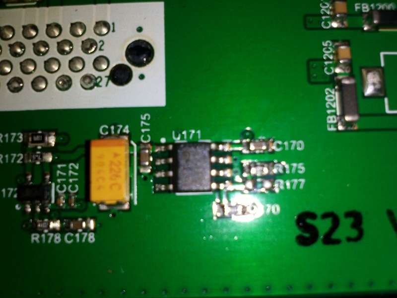 The pin with the white dot should read as 8 volts. It's only a 100mA output regulator - so it's a candidate for burning up. Part number LE80 (LE80CD-TR for example). |
||
|
|
|
| This user likes this post: |
|
07-10-2019, 11:30 PM
|
#21 | ||
|
Regular Member
Join Date: Oct 2019
Location: Adelaide, SA
Posts: 43
|
i checked LE80 and i am receiving mv all round.
on Q15N06-42L (the one with the middle pin missing) top pin im receiving 5.6v and bottom pin im receiving 11.89v. i might have popped this mosfet during my last test too... see attached.  I powered the screen separately using a 9v battery and then powered the unit, and noticed lines across the screen, similar to the image below. 
|
||
|
|
|
| This user likes this post: |
|
08-10-2019, 06:08 PM
|
#22 | |||
|
Away on leave
Join Date: Apr 2019
Location: ACT
Posts: 1,732
|
Quote:
The 11.89v comes from pin 5 on the large connector, it goes to the MOSFET and the voltage regulator's V-In (the one I think runs the front button LEDs). It also directly goes to pin 8 on the LE80 (the one directly across from pin 1, to the right). If that is only measuring mv, then the board has suffered a trace meltdown. The trace is in the layers of the circuit board (top and bottom of this board are generally grounded with very few traces). I've seen it before, but really, it shouldn't happen with such low value components - which is why I'm asking you to re-check. You "could" solder in a thin strand of wire (in case it's going to blow like a fuse) to see if you can get the 8v working again? I don't want to suggest bad things to do, but unless you start pulling out components (that show a problem) and replace them - this is what I might do (to be honest, I thought about your 9v battery idea, but wasn't going to mention it because of this very concern). Since this part isn't working, we really need to get it sorted first. The 8v may supply voltage to the other bits which cascade through the unit - and this one is "up front" because the 2 others are (/were, poor MOSFET) running off the 12v which is working. |
|||
|
|
|
| This user likes this post: |
|
08-10-2019, 06:54 PM
|
#23 | |||
|
Regular Member
Join Date: Oct 2019
Location: Adelaide, SA
Posts: 43
|
Quote:
Just at work, at the moment. Ill check soon. I had a small win today as well, sort of. I local wrecker as a few screens for sale ($365) from a SZ Territory, which looks identical to my screen, but not sure on the following and couldnt test their screen as they have a you break you pay policy. Im also worried that this could be already dead (even though they are saying it working) an Im stuck with the bill. As the people are saying in this forum that their screens have died just from disconnecting the battery. 1) Are the SZ screens compatible? 2) do they require reprogramming of any kind to work in a different car? |
|||
|
|
|
| This user likes this post: |
|
08-10-2019, 09:09 PM
|
#24 | |||
|
Regular Member
Join Date: Oct 2019
Location: Adelaide, SA
Posts: 43
|
Quote:
Ok, so i use an new grounding point in the car. and the 3 pin mosfet which i thought i blew, is reading at I (on) key position 11.89v @ top pin and 21.70v on the bottom give or take some mv's. On the II (accessories) and (Running engine) key position, i was getting 14.35v @ top pin and 10.30v on the bottom give or take some mv's. so that bottom pin is getting a 10v drop while the can is switch to accessories/running position. so i assume this is why the display inst turning on. - see attached image From memories I (on) position allows the radio to still play but no screen in normal circumstances. and when you put the key into the II (accessories) or Engine Start (running position) the display turns on. the 8 pin chip LE80 is still giving me 8mv at the top left pin (white dot), opposite that was 7.1mv and the rest were giving me under 5mv. the big 5 pin one is now giving me mv's at all pins too. both chips didn't vary with the car running or at the I (ON) position P.s how do you paste images to the post? i can attach, but when i paste it comes up as text. |
|||
|
|
|
|
09-10-2019, 05:51 PM
|
#25 | |||
|
Away on leave
Join Date: Apr 2019
Location: ACT
Posts: 1,732
|
Quote:
If you've got 11.89v and 21.7v while the key is in position I then that's what I've got on my bench. I've not measured it any other way (in the car / changing key positions) as I didn't seem to need to. I'm sceptical the reading on the large 5 pin device is correct, the trace is not burnt anywhere, and I've seen what happens on one that large when it pops. I'd suggest testing again (except you may be sick of pulling it out now, dealing with difficult forum members, and just want to get it sorted at ~$300). The 8v regulator, well, I feel bad about giving you a hard time, so I desoldered the 8v output on mine and it still turns on, lights up and displays everything normally. If it's not getting power on yours though, maybe other things are also not getting power. Connecting power to it with a wire may pass the power on to the other things? It actually makes sense, because I said I didn't think a 100mA thing like this would blow the trace - but if more things are using it, then yes, that's more reasonable. Last edited by JasonACT; 09-10-2019 at 06:05 PM. |
|||
|
|
|
| This user likes this post: |
|
11-10-2019, 09:48 AM
|
#26 | |||
|
Away on leave
Join Date: Apr 2019
Location: ACT
Posts: 1,732
|
Quote:
1/ I had just assumed you got things mixed up here, because while I got those voltages, my readings are reversed - 20v top pin, 11v bottom. 2/ Since it has popped it's possible the readings will be weird. 3/ That MOSFET is rated for +/-20v gate voltage (like many are). 4/ Mine only just exceeds the 20v maximum, so my repeated bench testing might not ever show the problem of the LCD dying. 5/ Yours is going well over! Typically, 10v is used in circuits, except for logic level MOSFETS that work on 3.3v-5.0v - so 20v is the max that should safely be passed into them. 6/ I think that MOSFET dims the display at night time, it's going to get hotter at that time, so it needs to be cooled. 7/ Jaycar don't have MOSFETs in the size you need, but there's a couple there which are larger (with the same +/-20v gate specs) which may work, except night time dimming will be an "unknown" because the board has been calibrated to work with a different one. I'd be looking at the IRF1405 - it has the same pinouts and I'd somehow add a small flat heatsink. (That's enough thoughts.) |
|||
|
|
|
| This user likes this post: |
|
07-10-2019, 11:55 PM
|
#27 | ||
|
Away on leave
Join Date: Apr 2019
Location: ACT
Posts: 1,732
|
Oooh, that black dot wasn't there before. You will be up for a new mosfet then (I'm glad you identified what it was too - I hadn't mentioned it before because it's not a regulator, and it didn't change values for me when the screen was on or off - so whatever it's switching isn't the screen directly).
I'll do some more tracing tomorrow after work, to find where the +20v is generated from. That would seem to be the "thing" for the screen to light up (at least). I'm not quite sure what you mean by "mv all round"? |
||
|
|
|
|
08-10-2019, 12:10 AM
|
#28 | ||
|
Regular Member
Join Date: Oct 2019
Location: Adelaide, SA
Posts: 43
|
sorry, when i tested the LE80 chip, i didnt receive 8volts, just millivolts at all pins..
so as i was testing voltages on the 5 pin chip, i accidentally touched 2 of the pins at the same time, and popped a hole in the mosfet opposite to it (the 3 pin one) as you can see in the image. But i think you may be onto something, with that 8 pin chip as i wasnt receiving 8v from that either.... I think these guys in the link below have worked out what the problem is with these screens and exchanging them, as they are charging $716 for an exchange screen. so i assume that they fix your old one, and give you another repaired one they have fixed previously. https://www.aslautomedia.com.au/falc...creen-exchange |
||
|
|
|
|
08-10-2019, 12:16 AM
|
#29 | ||
|
Regular Member
Join Date: Oct 2019
Location: Adelaide, SA
Posts: 43
|
ok so the red/black wires are just to power the back-light of the LCD.
i noticed these lines as i had angled the LCD around - no back-light illumination. I thought to manually power the back-light with a 9v volt battery just to illuminate what the LCD was producing. Whenever id pull the power from the FDIM but leave the power to the back-light on, the lines would disappear. So these lines are definitely something that the board is producing. |
||
|
|
|
|
11-10-2019, 08:07 PM
|
#30 | |||
|
Away on leave
Join Date: Apr 2019
Location: ACT
Posts: 1,732
|
Quote:
It doesn't matter if the screen is on or off for me, if the 12v is applied to the large external connector for the car loom, the screen remains off and I get 21.45v on the gate pin (enabling the MOSFET). When I switch the screen on, that drops to 20.3v (still enabling the MOSFET). 12v power is going through the MOSFET and powering the large regulator, the 8v small regulator and the small unknown device - and is also sent into pin 5 of the board joining connector. The original 12v is coming in from pin 1. I'd say there's a timer that eventually switches the MOSFET off in a deep sleep mode to save power, but it doesn't happen in the first few minutes. Since you are getting dodgy voltage readings, the MOSFET still needs to be replaced before we can continue. Pin 5 must power something else on the large board related to the screen, and I've found two components of interest (one is very close to the red and black wires). That one is a TSSOP 16 device, I hate this one, the entire bottom is a ground which gets soldered to the circuit board as a heat sink - making it impossible to remove without damage. I just rip the legs off them and leave them there. You need to get a TSSOP 16 breakout board to use them - but I don't see any with the ground/heatsink and a heat gun might be needed to get the base soldered properly anyway. It's an LT3517 (Linear Technology) LED Driver with 1.5A switch current. It'll be doing the brightness control. They are available on ebay from China. The less likely chip (further away and closer to the audio components on the large board) is a MSOP 10 device, I hate all of these, you guessed it, bottom is a ground/heatsink. You need a MSOP 10 breakout board..blah..blah.. Those do have a heatsink. It's got LTDXS written on it (Linear Technologies) which is their code for LT3972 - 3 Amp power regulator. Also available on ebay from China. Would I try any of this? (Well, I have before, so that answers that.) At $700 for an exchange, I would again. $365 is sounding like an OK deal though, as I did buy a backup at around that price (which I didn't know had SAT NAV). That was also to do bench testing though, as I knew my ultimate project of getting the FGX Sync 2 unit working would require all the CAN BUS codes I could get from a MK2 unit first. (Side note, I still don't have all the codes - I keep finding things I don't use - but at least I wouldn't miss them.) I really hope it's just the MOSFET on the small board. |
|||
|
|
|


 Hybrid Mode