
|
|

|
|
|
|
Welcome to the Australian Ford Forums forum. You are currently viewing our boards as a guest which gives you limited access to view most discussions and inserts advertising. By joining our free community you will have access to post topics, communicate privately with other members, respond to polls, upload content and access many other special features without post based advertising banners. Registration is simple and absolutely free so please, join our community today! If you have any problems with the registration process or your account login, please contact us. Please Note: All new registrations go through a manual approval queue to keep spammers out. This is checked twice each day so there will be a delay before your registration is activated. |
|
|||||||
 |
|
|
Thread Tools | Display Modes |
 16-04-2007, 03:23 PM
|
#1 | |||
|
You can't stop the signal
Join Date: Nov 2005
Location: Behind a computer at work
Posts: 1,624

|
Well you all have been waiting for a while and here it is.
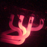
I apolisge for the wait as i got snowed under with stuff and even now i still haven't got on top of every thing. Enjoy (Note, a copy of this will be sent to casper for aufalcon.com) This has been written off my memory and the photo's that i have taken. This should work but an actual test of the tutorial has not been done __________________________________________________ __________________________________________________ _____________ How to install height adjustable switches for your power aerial Parts needed: Various screwdrivers, flat and Phillips headed Various colours of electrical wire (E.g. Black, red, blue, green) Soldering iron and solder Electrical tape (must) and fabric tape (if wanted) Wire cutters Various male and female crimp terminals (red size preferred), ensure female spade terminals will fit over relay pins 5 pin relay Two power diodes (must handle at least 2 or 3 amps, I used a 400v 3A power diode) Two momentary pushbutton switches With the switches for the aerial, it is really up to what buttons or switches you use. For my installation I used two momentary pushbutton switches from jaycar(see below), however if wanted a momentary toggle switch or even something completely different, you probably could. (PM me of ford forums if you want to wire it differently to what I have described) 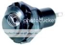 CAT. NO. SP0700, $2.80 per item Small Black SPST N/O Momentary Action Very attractive small round momentary push on switch, with black body and black actuator, rated @ 1.5A 250 VAC. Cutout is 12.5mm.  The way I have wired my buttons is that one will bring the aerial up to any height I want and the other will bring it down to any height I want. Then once the car is turned off, the aerial will be brought fully back down. Before staring, please ensure that you have enough and the right components. Since this removes the center finish panel, it is not advised that your car be driven with this removed. DISASEMBILY Before beginning disconnect the negative battery terminal and wait a couple of minutes. This disables the cars electrical system and the airbag system. Also while working on the car, ensure there are no keys in the ignition at any time. Step 1: Removal of radio The way in which to remove the radio will depend on whether the radio system is standard or if it is an aftermarket system. To remove the standard ford system, you need to fabricate two tools(see Figure 1) out of 3mm wire and insert this into the access holes deep enough to release the locking pins. Then withdraw from the vehicle. 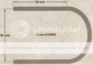 Figure 1 It should be as simple as to insert the locking keys so that the radio unit releases from the cradle and then withdraw from the car. Please note, that the center finish panel also has to be removed so depending on how your system was installed the radio cradle will most likely have to be removed as well Step 2: Removal center finish panel Remove the glove box from the vehicle. Open the glove box and disengage the limit pins by pulling the sides of the glove box inwards (figure 2). Lower the glove box and firmly lift the right hand side corned to disengage the hinges. Maneuver the glove box from the dash. (Figure 3)  Figure 2: glove box with limit pins disengaged 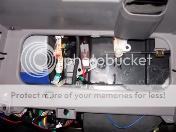 Figure 3: glove box removed Unlock the plastic clamp securing the temperature control cable wire to the heater assembly temperature lever. This will require the use of a small flat bladed screwdriver. You need to get the blade between the head of the clamp and the clip which is located on the bottom of the clamp. When screwdriver is in place, simply twist to release the clamp. Remove the wire from the clamp (figure 4). Then remove the temperature control cable from the metal clip. This will require you to bend the outside of the clip up while pulling the cable down (figure 4). It is recommended that the end of the cable to taped up so to protect your dash from scratches, however if you are careful and confident this is unnecessary. 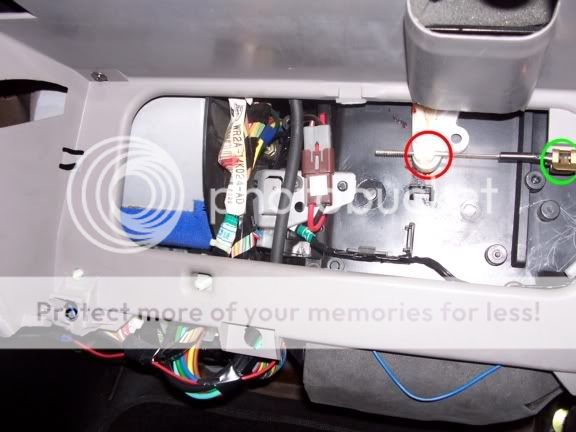 Figure 4; Plastic clamp (red circle), metal clip (green circle) Disconnect the vacuum supply hose from the T piece (figure 5, red circle) in the vacuum hose harness. Disconnect the 8 port vacuum hose (figure 5, green circle) harness connect beneath the air intake duct. Release the clips (figure 5, purple circles) retaining the loom to the dash. This will require the use of a small flat baled screw driver to prise the clips off.  Figure 5: T piece, hidden (red circle). 8 port vacuum hose, half hidden (green circle). Clips, hidden (purple circles) Remove the ashtray and undo to four screws holding the center face in place. There are two in the radio slot, and two behind the ashtray. (figure 6) 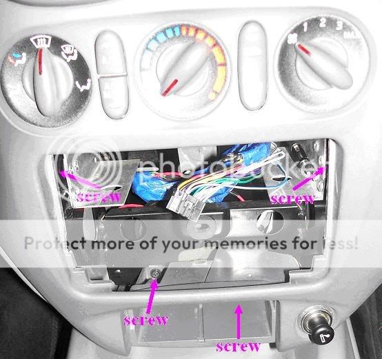 Figure 6 Gently prise the center finish panel away from the dash, but not entirely away, pulling the 5 metal clips away with the panel. If any of the clips detach from the center finish panel, simply reinstall them, or better yet superglue them back into place. This will ensure that the clips will stay in place and that the dash will fit snugly back onto the dash. This also goes for if any of the clips break or are already broken, just simply superglue them in place, since it is rough $4 + per clip from ford to replace them. Disconnect all of the wiring harness from the center finish panel. This will include the cigarette plug and globe, two for the heater controls, two harnesses behind the demister button 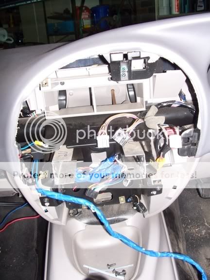 Figure 7: Center finish panel removed WIRRING AND INSTALLING SYSTEM Note: The length of wire need will depend on the position that the switches are located, the position of the relay, and where the aerial wires are located. Step 1: Mounting the Relay The purpose of this relay is to supply power to the aerial when the car is switched off, so that the aerial will retract fully. The position of the relay will depend on personal preference. I found that mounting it to the metal from that holds the stereo in place the easiest (figure 8). This was due to the fact that in this position it does not foul any panels, it is an open area allowing wires to be easily attached, and the metal frame acts as a grounding point for the relay. 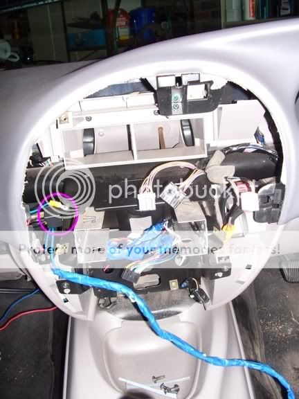 Figure 8: relay and earth cable Firstly, decide where to mount the relay. Remember that where you choose to mount the relay, you must be able to have enough access to mount it securely. Find a self tapping screw that will fit through the mounting tab of the relay and that is about ½ inch (12mm) long. Then find a drill bit that is approximately 3mm small than the screw. Install this in a drill and drill a hole through your chosen mounting location. Ensure that there is nothing being the hole that you are drilling that will be damaged. Now attempt to install the self tapping screw, until it is fully seated against your mounting point. This will require a fair amount of force, however if you find that it is to difficult to screw in, remove the screw and step up to the next biggest drill size you have and re-drill the hole. Ensure that the drill bit you use is not the same size or bigger than that of the screw, else the screw will not grip. Once the screw will seat against your mounting point remove it and store it until later. Now cut your self about 10cm of wire, any colour will do (you can see I used blue) however ground is generally black, and strip both ends of the wire. At one end crimp a female spade terminal and at the other, an eye terminal that your self tapping screw can fit through. Once done, wrap the female spade terminal in electrical tape, so that all the metal is covered. Then connect to pin 85 of the 5 pin relay, and bend the wire so the eye terminal sits close to the mounting hole in the relay. Step 2: Installing switches There are two things to consider when mounting the switch to control the aerial. Firstly, location. Will you be able to reach it while driving? Is it easy to press the buttons? Does it look out of place? Secondly, mounting position. Theres little point in attempting to mount the switches in a location that requires half the dash to be taken apart to be able to mount them. That is why I chose to mount mine in the center finish panel, just under the demister button. Of course, the position that you will be able to mount your in will depend on the trim level of your car, whether it is a sedan, ute or wagon, and any other devices you have installed. I will describe how I mounted my switches in an AU 1 ute, with a low series dash. (Figure 9)  Figure 9 Firstly, decide where on the demister surround that you want to mount the buttons. Pay attention to the back of the surround too, as where it sits in the center finish panel, will depend how much plastic will have to be removed. Once decided get a spirit level and mark a line in grey lead across this panel. This is not necessary, however for looks is will make lining up the two buttons to level very easy. Mark the line with crosses where you want the two buttons to sit in regards to each other. Detach and remove the surround panel that goes around the demister button, by releasing the four tabs that hold it in place with a small flat bladed screw driver. (Figure 10) 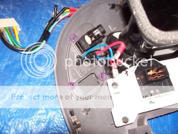 Figure 10: clips circled, 1 out of view Now holding a ¼ inch (6mm) drill bit in you hand, use moderate pressure while turning the drill bit to begin a hole in the surround. Take enough plastic out so that there is about a 1-2mm round circle in the mounting location you want. Now, install a ⅛ inch (3mm) drill bit into a drill and holding the surround in one hand against a bench (or wooden block, but must be wood), slowly drill through the surround. When fully through continue to increase the hole size in 1 or 2 drill bit size increments until the buttons will fully fit through. If you find that you need to use a drill bit that is larger that what the drill will take, simply grip the bit with pliers or better yet, vice grips, and turn the hole by hand. The plastic is soft enough to allow this and the pliers simply give you some leverage. Repeat this process for the other button as well. Once done, rub of the pencil mark with an eraser. Once the surround can fit the buttons, reinstall the surround panel into the center finish panel and see if any plastic from the center panel has to be removed. If some does have to be removed, this can either be done with a drill, hacksaw or a file. Any way is fine as a neat edge is not required on the center panel, since the surround hides this area. Just be careful to ensure that the face of the center finish panel does not get marked or damaged while doing this. As you can see, I had to take some plastic out of the center finish panel due to the position of my switches that I chose. (Figure 11/Figure 12) 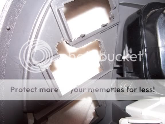 Figure 11 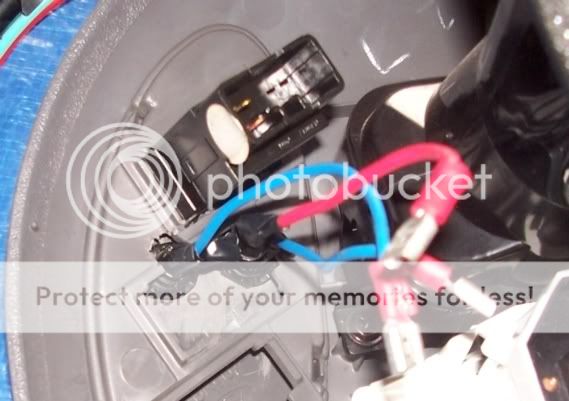 Figure 12 When completed installing the buttons into the surround and modifying any parts needed, fit the surround to the center finish panel to check that everything fits fine. If it does, remove the surround from the center finish panel, and move onto wiring the system. Step 3: Wiring the system The system has to be wired in this way for it to work correctly (figure 13). If the way the system is wired is modified or different parts used (apart from crimp terminal) I cant guarantee that the system will work, or do not take responsibility for any damage that it may cause. As an example, signal diodes cannot be used as the will fail quickly. I blew two up as I originally used them to get the system working. 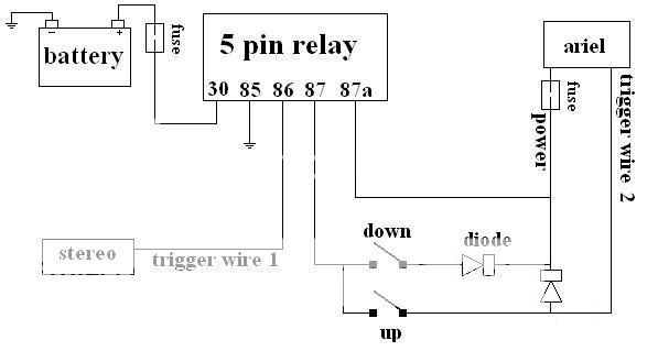 Figure 13: wiring diagram Firstly, wire up the buttons. For this you will need 4 pieces of wire, in two different colours (2+2, I would recommend red and blue), roughly 10cm in length. Solder a red wire to one terminal and a blue to the other terminal. When cool, wrap the joins in electrical tape and cut the red wire about 3cm from its end. Repeat for other button. Now install the buttons into the surround with the red wires facing each other. Get the free ends of the red wires, twist together and solder. Then solder on a 3cm length of wire so that all wires coming off the buttons are the same length. Cover this joint in electrical tape. When done, crimp female spade terminals onto the end of all 3 wires. (see figure 14) 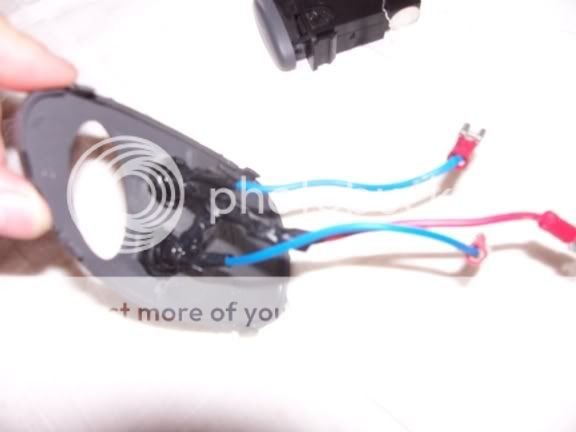 Figure 14: switch wiring (note: with the join where I have it, the switches cannot be withdrawn slightly form the surround, and it is fiddly to have it here) Now it is time to wire up the main part of the system. Cut two different colours of wire (one up, one down. Eg. blue and yellow. This is needed because once the wires are wrapped up you will be unable to recognize which wire is up and which is down. I didnt do this but I wrapped the end of one wire in yellow electrical tape) about 85cm long (can be shorter). Crimp male spade terminals onto one end of each wire. Now solder the diodes with the line away from the wires (see figure 15), or the system will not work. Cut 50cm lengths of each colour of wire. Crimp male terminals onto one end of each wire. On one wire and diode, solder this 50 cm pieces after the diode (this is now the down wire, see figures 15), and on the other, solder the 50 cm piece before the diode (this is now the up wire, see figure 15). Try to match the wire colours when solder on addition wires in this step Now cut a 15 cm length of down coloured wire and solder this to the down wire (wire with join after the diode (on the line side)) after the diode. Crimp a fmale spade terminal on the other end. Now you need to join both wires together. For this step, you need to join the end of the up wire(wire with join before diode), at the diode end , onto the down wire, after the diode. (see figures 15) 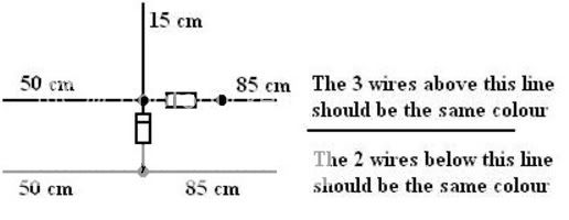 Figure 15 A: What wiring needs to be 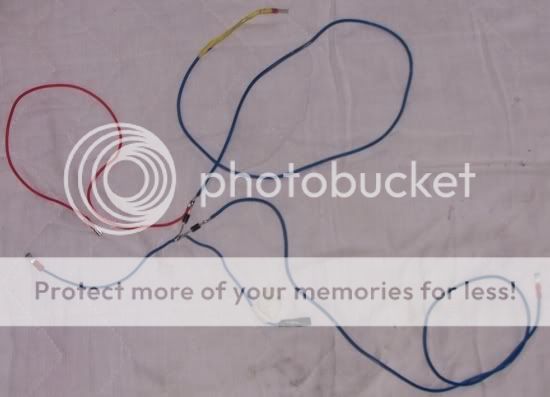 Figure 15 B: My wiring loom Once this is done, wrap the soldered connections up in electrical tape. Wrap each join separately. Now you need to cut 85cm of red(power) wire and crimp a male terminal onto one end, and a female spade terminal on the other. Group this wire with the other 85cm long button wires, with the male terminals all at the same end. Then wrap the entire loom together in fabric tape, grouping both sets of longer wires together while leaving the 15cm wire free. On the longer 85cm grouping, leave the last (diode end) 20cm of the red wire free. Now with this main part of the system completed, the simple hook up wire needs to be done and the aerial loom spliced. Cut up two colours (red and another colour) of wire into 70cm long. These are you main power wire and trigger wire. Crimp female terminals onto each end and leave the other ends free for the moment. Now determine what, if any terminal you stereo trigger wire has attached to it. This wire is usually call the aerial, accessory wire or amp wire, and should be used as a trigger only. If it has no terminal on the end, you can crimp one of you choosing on, then the opposing terminal onto the other end of your 70cm long trigger wire. However if it has a terminal on it, simple crimp the opposing terminal onto the end of your 70cm long trigger wire Moving away from this, you now need to determine where you will draw power from for this system to work. Note. it needs to have power regardless of ignition switch position, as this allows the aerial to fully retract. I have piggy back my power wire into the same constant power wire as the stereo. While not ideal, both systems are fussed (fuse box, and an inline fuse on the power wire of this system), and the location made it easy enough. To do this you need to cut the constant power wire to the stereo and crimp a piggy back terminal onto one end and the opposing terminals onto the other side of you cut, and the other end of your power wire. The final step in wiring the system is to splice into the power aerial wires. However, since I fitted an aftermarket aerial then performed this mod, I dont fully know where wires run, or which wire is which. Firstly, find the two wires from your power aerial. They will run though a rubber grommet along with the thick black antenna wire, in the passenger foot well. You may need to peel back some of the carpet/matting to find this grommet. The wire colours should be, red with a white run, and yellow with a green run. Follow these wires along, and assuming the run underneath/behind the glove box, I would cut them there, towards the right hand side of the glove box. If they dont run here, find the easiest location to cut them in that suits you. Note, if you change the location of the cut, your length of the 85cm wire will either need to be lengthened or shortened to match. Now once cut, crimp female terminals onto their ends. Now you will need to find out which wire is the power wire and which the trigger wire is. To do this, you need to supply power to both wire at the same time, this should bring the aerial up. Bring the aerial up to full height and disconnect both wires. Now, if you connect power to one wire only, one should bring the aerial down, while the other will make a clicking sound (may not be loud enough to hear). The one that brings the aerial down is the power wire, while the other one that makes the clicking sound is the trigger. Step 4: Connecting the system up Before beginning, I would recommend that the female spade terminals that will connect to the relay be wrapped in electrical tape to hide their metal components. This is a precautionary step, to reduce the risk of short circuiting. Now hold your 5 pin relay in your hand. Connect your designated power wire to your power source and electrical tape the connection. Connect the other end to pin 30 of your 5 pin relay. Now connect your trigger wire to the stereo trigger wire, tape connection, and then connect the other end to pin 86. Grab your main connecting wiring (piece with diodes in it), and connect the 85cm long red to pin 87 of the relay. Now connect the 15cm long down coloured wire to pin 87a of the relay. Now feed these wires into the dash, ensuring that the fascia can be put back on, and also pulling both the up and down coloured wires out of the bottom of the dash at the glove box. Screw the relay into place with the screw you used earlier. Connect the down coloured to the power wire of the aerial, and the up wire to the trigger wire of the aerial. Now tape any free connection in electrical tape (apart from the button joins). Finally you should give the system a test run. To do this you need to reinstall your stereo (Just sit it in its place) and connect up the red 85cm long wire to the red wire on the buttons, and then the blue wire to the other two wires. While this test is in progress, ensure these connections do not touch the chassis, or each other. Reconnect the battery, and turn the stereo onto the radio. Now operate the buttons. One should bring the aerial up, and the other should bring it down. Now turn the stereo off, and the aerial should be brought back down fully into the quarter panel. If all this works successfully, congratulations, you have successfully wired the system. At this stage decide which button you want to be the up button and which one you want to be the down button. Once decide and connected, remember which wire is connected to each switch. Disconnect the buttons and remove the stereo. Step 5: Reinstalling the center finish panel Reinstall the button panel into the center finish panel, ensuring no wires are caught. If any of the clips on the back of the center finish panel, superglue them back into place now, if you havent done so already. Installation is the reverse of removal, paying attention to the following points 1. Connect the button wiring up as it was before, with the up and down buttons as you like. Cover the joins in electrical tape. 2. Run the wiring to the switches below the heater duct and above the heater controls. 3. Carefully guide the vacuum hoses and cable through the aperture in the dashboard and partially install the radio surround panel. Ensure the vacuum hoses and cable are positioned correctly 4. Connect the wiring to the heater controls and the cigarette lighter and install the surround panel to the dash board. Tighten the retaining screws 5. Install the sound system and ashtray. 6. Set the temperature control by positioning control the knob to full cold and the heater assembly temperature lever fully anti clockwise. Connect the inner cable to the lever on the heater unit and then install the outer cable to the retaining clip. 7. Connect the vacuum supply hose to the T piece 8. Install the glove box. Congratulations, You now have you height adjustable switches installed and working properly. Enjoy References Gregorys workshop manual for the au falcon (1998-2002), No 274 Jaycar catalog 2006 Fordforums.com.au and its kind members Written by superroo, for aufalcon.com. ©2007
__________________
Quote:
|
|||

|

|
|
16-04-2007, 05:05 PM
|
#2 | ||
|
Miami Pilot
 
Join Date: Jan 2005
Location: ACT
Posts: 21,700
|
Great writeup!
__________________
-----------------------------------------------------------------
The Hammer: FG GTE | 376rwkw | 1/4 mile 11.793 @ 119.75mph 1.733 60' (4408lb) 1 of 60 FG MK1 335 GTEs (1 of 118 FG Mk 1 & 2 335 GTEs). Mods: Tune, HSD/ShockWorks, black GT335 19 staggered replicas with 245 & 275/35/19 Michelin Pilot sport 5s Daily: BF2 Fairmont Ghia I6 ZF, machine face GT335 19 staggered Replicas with 245s and 275s, Bilsteins & Kings FPV 335 build stats: <click here> Ford Performance Club ACT |
||
|
|
|
|
16-04-2007, 05:59 PM
|
#3 | ||
|
[ 5L ]

Join Date: Oct 2005
Location: North Haven, Adelaide
Posts: 2,886
|
i might have to give that a go, im sick of the xr8 looking like a rc car when the aerial is up.
__________________
[ 5L ] 2001 AU series 2 xr8, 220kw, 5speed, leather interior, premium sound, narooma blue, cat back exhaust, k&n filter,willall edit,MSD coil packs, MSD leads, monroe gt gas shocks, superlow kingsprings 187rwkw (mainline) www.ignitionimages.com
|
||
|
|
|
|
03-06-2009, 03:16 PM
|
#4 | ||
|
Starter Motor

Join Date: Nov 2006
Location: Davoren Park, South Australia
Posts: 20
|
Would I have to remove everything behind the glove compartment if I just want to get to the globes in the rear of the centre finish panel?
I bought an ex-taxi and ALL the display lights are blown.
__________________
Regards ... Robert Why do today that which you can put off until tomorrow? |
||
|
|
|
|
03-06-2009, 04:22 PM
|
#5 | |||
|
gone fishing

Join Date: Jul 2006
Location: Morayfield qld
Posts: 286
|
Quote:
but on a series 2 and 3 you can replace the lights. hope that has answered you question. cheers
__________________
Cheers Whiskers |
|||
|
|
|
|
03-06-2009, 09:22 PM
|
#6 | ||
|
Starter Motor
Join Date: Nov 2006
Location: Davoren Park, South Australia
Posts: 20
|
Sorry, shoulda' said. May, 02 Falcon Sedan, Model #18233, which isn't listed in my Ellery, so I don't know whether Forte or Futura or SR or what as the vehicle was basically de-badged except for the Falcon across the boot and the Series III on the boot.
Anyway, found I couldn't get to the back of the centre console without removing at least the temp control cable, so the question is now moot. I did find out today that the orange globe for the Air/Con switch is NLA. I'll get a 3mm vanilla globe and fit it myself to the base, probably from AZ Tronics. Anyway, I haven't had this much fun since I bought the EA-II in 2003 and started to fix that up, no special mods as such, just getting everything working properly with all globes and sensors plus whatever else is missing back to factory, you could say I am blueprinting the car. :-)
__________________
Regards ... Robert Why do today that which you can put off until tomorrow? |
||
|
|
|
|
04-07-2009, 07:59 AM
|
#7 | |||
|
Starter Motor
Join Date: Nov 2006
Location: Davoren Park, South Australia
Posts: 20
|
Quote:
I bought an original AU-III aerial and I'm deciding whether to do this or just get the BEM for the aerial height switch. I know that's just half or full, but I think it would be a lot easier. I haven't been able to find anything that tells me what I need to sit the aerial into the fender. There isn't any metal seat under the skin like on the E series, is there a plastic piece like the XH ute has? Would like to know, there is nothing in the Ellery's on this. I'm not able to afford the Ford workshop manuals for the AU series, over $350 just for the 1st volume.
__________________
Regards ... Robert Why do today that which you can put off until tomorrow? |
|||
|
|
|
|
04-07-2009, 09:35 AM
|
#8 | ||
|
FF.Com.Au Hardcore

Join Date: Nov 2008
Location: Melbourne, Vic
Posts: 1,121
|
under the plastic inner guard there is a bolt like thing that is welded onto the car. The ariel will have a bracket which will sit over it and you just need one nut to then attach it. The earth for the ariel will screw back in where the original manual ariel was attached.
Hope this is of some help
__________________
AU III Forte wagon - V8, 5spd man, lowered, 18" Honeycombs, Stock diff rebuilt with TruTrac LSD, Leather Ghia interior/dash, custom twin 2.5" into single 3" exhaust. Wagon Build AU I Forte Sedan - No longer
Toy Car Build |
||
|
|
|
|
04-07-2009, 12:17 PM
|
#9 | |||
|
Starter Motor
Join Date: Nov 2006
Location: Davoren Park, South Australia
Posts: 20
|
Quote:
I know the completed assembly looks like there is just a grommet at top, but there has to be something to hold the aerial in place as well. A support that the chrome nose screw down to, maybe an insert that sits into the hole, maybe. The problem is nobody seems to know for sure, not even the Ford people at spare parts. I was hoping someone here has an auto aerial on their AU and would be able to show/tell me what I am missing.
__________________
Regards ... Robert Why do today that which you can put off until tomorrow? |
|||
|
|
|
|
04-07-2009, 08:08 PM
|
#10 | ||
|
Starter Motor
Join Date: Nov 2006
Location: Davoren Park, South Australia
Posts: 20
|
OK, have got the proper top for the aerial. I asked the bloke at U-pullit (self serve wrecker) what I would need to get off the car for my aerial.
What it is, is a plastic grommet that clips into the hole in the fender with another clip arrangement to hold the top of the mast barrel in place. The top of the mast barrel has a screw on cap with a ridge around the top, this ridge then clips tightly into the bottom of the grommet under the fender and with the bracket at the base of the aerial assembly bolted to the bottom of the fender it is held very firmly. You have to take the fender off to get under it so you can get the grommet off. Apparently it is the same for the EF/EL aerials. If my car had the original manual aerial it would have been the same grommet, but it had been replaced with a "rubber ducky" type before I got it.
__________________
Regards ... Robert Why do today that which you can put off until tomorrow? |
||
|
|
|
|
10-07-2009, 07:01 PM
|
#11 | ||||
|
Starter Motor
Join Date: Nov 2006
Location: Davoren Park, South Australia
Posts: 20
|
Quote:
.
__________________
Regards ... Robert Why do today that which you can put off until tomorrow? |
||||
|
|
|
|
14-07-2009, 12:22 PM
|
#12 | |||
|
You can't stop the signal
Join Date: Nov 2005
Location: Behind a computer at work
Posts: 1,624
|
The way that I have done it, the aerial will stay down when the car is turned on, or when the stereo is switched to radio. You have to bring the aerial up to the height up want no matter what.
If you wire it to the BEM I believe it will come up to the height that you last had it at, but I can't confirm. Cheers
__________________
Quote:
|
|||
|
|
|
|
27-08-2009, 03:25 PM
|
#13 | |||
|
WAGONE

Join Date: Jul 2006
Posts: 426
|
Quote:
Anyway still if you listen to cds a fair bit its really good. |
|||
|
|
|
|
03-06-2013, 06:01 PM
|
#14 | ||
|
Starter Motor
Join Date: May 2013
Posts: 1
|
Hello there,
Today i tried doing your adjustable antenna mod and Its doing strange things. When I push the Up switch I have 12V on the power wire and the trigger wire of the aerial but it doesnt go up. Any ideas? Also, despite having the diodes correctly installed when i push the down switch I appear to have 12V on both the power wire and the trigger which is incorrect yes? I'm stumped, I believe i followed your wiring diagram correctly. Perhaps the antenna motor is internally fused or something. But even when i removed the connecting diode from the up and down circuits, there was still power on the trigger wire when i pushed the down button. Thank you in advance for any advice. |
||
|
|
|


 Linear Mode
